


field calibration procedures.
-
Go to level on face 2 display and level the robot by zooming in all the way to 1:10 level bubble.
-
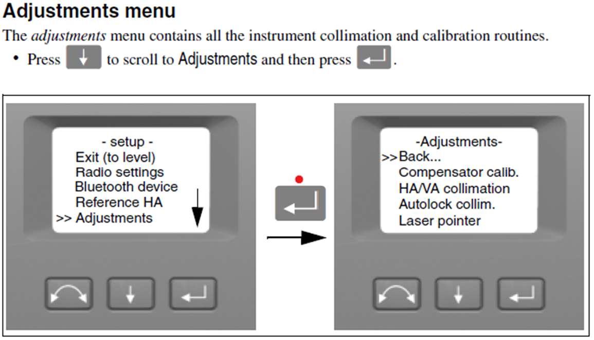
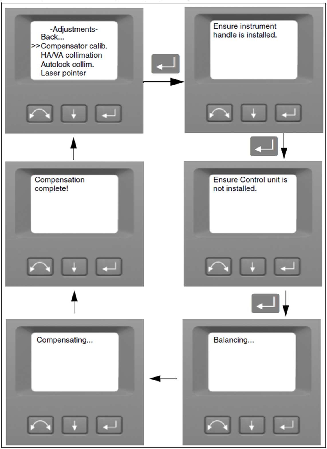
Go to setup from level bubble screen and arrow down to adjustment, run compensator calibration. (See pics below)
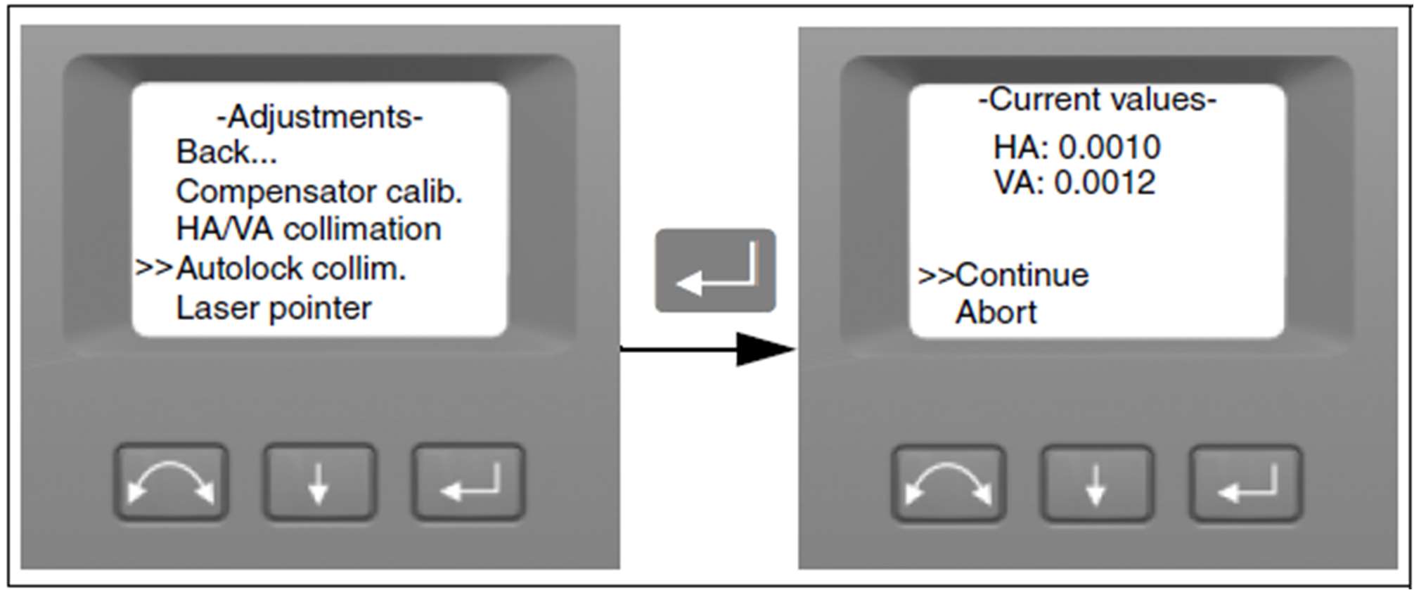
HA/VA Collimation
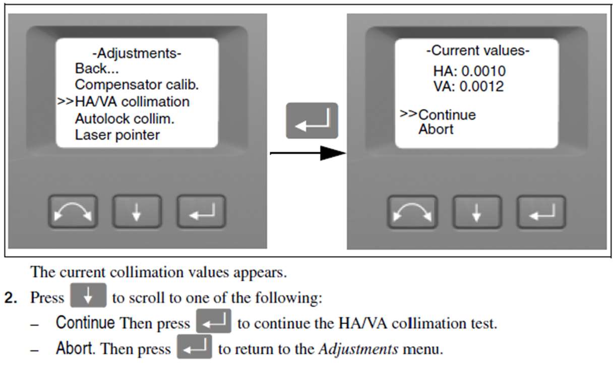
Using the same setup for the compensator calibration arrow down to the HA/VA collimation and press enter. This
calibration requires an object at least 100m (330 feet) or further. (i.e., screw head, target drawn on blue tape, etc.) Not
recommended to use the prism!
- Look through the eyepiece and aim the crosshair at the object you set above (nail head, target, etc..) Aim the very best that you can, keeping the crosshair in focus and the target in focus. Arrow to new observation and tap enter. (This will internally record the measurement and on the screen, it will show Face 1 obs:1)
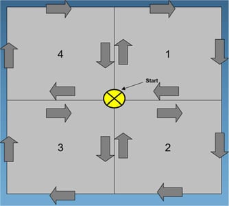
- Using the dials on the side of the RTS, move the crosshairs in a pattern similar to the picture below. Repeat the above procedure and press new observation every time. Do this method at least 3 times in Face 1 pressing new observation after adjusting of the target every time.
- Next arrow down to select switch face, be aware the RTS will start to move as soon as you press enter. It will spin 180 and scope flip 180.
- Repeat aiming process and steps above in the Face 2 aiming at the target 3 more times. This time Face-2 obs: will start to count up. Once you have down Face 2 the same amount of times as Face 1 the robot will display the new calibrations done internally.
NOTE: If an error is greater than 45” seconds it will fail. Repeat the process to ensure you didn’t mess up. If it fails 2 times
call the office and then Trimble. Something is wrong at this point.
- When done arrow down to Store and press enter. Switch robot face 180 degrees to return to normal layout position.
Tracker / Autolock Collimation
- Next take the prism/rod/bipod and set it up at least 100m or 330ft away from the robot. The MT1000 should be at the roughly same elevation as the RTS.
- From the same adjustment screen arrow down to Tracker Collimation and press enter.
- Arrow to continue and press enter.
- Accurately aim the RTS scope at the MT100.
- Select new observation, this will start another automatic sequence that should last a few mins. Be aware the RTS will start moving on its own.
- During this process make sure nothing crosses in-between the RTS and the MT1000, or the measurement will fail.
- Once the RTS is finished the task is finished, return to level screen to check level, and continue as normal.
Minimum Robotic Instrument Field Procedures
Accuracy/Precision
- Accuracy and precision are key because with radial staking there is little ability for redundant measurement checks.
- Measurement Stability: Optical total stations require sufficient time to adjust to the ambient temperature. Use the following rule of thumb before attempting a high-precision measurement: Temperature difference in degrees Fahrenheit equals the number of minutes required for the instrument to adjust to the new temperature. Not required for typical construction layout.
- The maximum layout distance shot in with these instruments should typically be < 750 feet.
- The setup anywhere function in FieldLink shall be used with 3 points minimum in order to provide a check.
- Horizontal and when needed vertical control checks will be made at the beginning and ending of each new setup and throughout the day.
- Point staking records will be stored at each point staked in FieldLink.
Trimble RTS Field Collimation and Calibration Schedule
- At each new occupation (and throughout the day if you do not occupy new points from time to time), Check the temperature on a thermometer or phone and enter the new temp in FieldLink.
- Daily (or possibly more often when temperature conditions vary) On the RTS Face 2 display, under the Adjustments... menu run the Compensator calibration adjustment routine
- Daily (or possibly more often when temperature conditions vary) On the RTS Face 2 display, under the Adjustments... menu run the Horizontal/Vertical Angle adjustment collimation routine (at a target distance of at least 350 ft.)
- 1-2 times per week (or more) On the RTS Face 2 display, under the Adjustments... menu run the Tracker collimation adjustment routine on a target at least 350 feet away.
- As necessary, On the RTS Face 2 display, under the Adjustments... menu run the Laser Pointer adjustment routine.
- Monthly (or possibly more often if setting up over a known point), Check the Optical Plummet by the following procedure:
- Set up the instrument and level it over a ground mark so that the tripod height is about 5.0 feet.
- Note the position of the inner circle of the optical plummet in relation to the ground mark.
- Turn the instrument 180 degrees.
- Note the position of the inner circle of the optical plummet in relation to the ground mark. If the inner circle of the optical plummet reticule moves in relation to the ground mark, you must send the tribrach in for cleaning and adjustment.
- Monthly, Occupy at least two EMH&T office traverse control monuments and make horizontal distance, vertical distance and angular checks.
- 1-2 times monthly (and as necessary) Check prism poles and bubble to be sure they are plumb and check extension sections to be sure they do not have any bends.
- Yearly, Send in instruments and tribrachs to be cleaned and calibrated.
Reasons Why We do Field Calibrations:
HA/VA Collimation. The collimation routine consists of the HA/VA collimation and then the trunnion axis tilt. The Horizontal and Vertical collimation and the trunnion axis tilt correction have been measured and stored in the instrument at the factory.
The RTS instrument utilizes precise angle and distance measurements to determine the position of the point being measured. The instrument's design facilitates the ability to measure all points with a single pointing to the target in the Face I position. All electronic total stations are subject to collimation errors in both the horizontal and vertical angle measuring systems, and also errors caused by the axis of the telescope not being truly perpendicular to the vertical of the instrument.
In order to compensate for these errors, the collimation routine allows the operator to accurately determine the current errors in the instrument, and store the errors as corrections to be applied to all measurements made in a single pointing to a target. In this way, the S Series Total Station will always provide accurate measurements.
The Collimation errors and Trunnion axis tilt will change over time, the commonest changes being caused by
- Wear and tear with use
- Bumps and knocks during transit
- Large changes in operating temperature Trimble recommends that a collimation check and tilt axis check be carried out routinely as follows
- After any long uncontrolled transport of the instrument (e.g. after service or shipment to a new location)
- After any accidental knock or drop
- At any time when the operating temperature changes by more than 10
- C (18 •F)
- At any time when the instrument changes the height above sea level by more than 500m (1640 Feet)
- At any time when the highest precision positions are required
- Routinely on a periodic basis (Monthly, weekly etc.)
Trimble also recommends that the operator keep a record of the dates and values measured so that any gross changes can easily be detected. Gross changes can indicate the need for a check by an approved service center.
In all calibrations, multiple sightings will be made in both faces to ensure that any minor pointing errors can be eliminated in the accurate determination of current collimation error values.
In a new instrument, the values should be close to zero, over time these will change. The instrument allows a maximum value of 0.05 grads (0.045 degrees) in the HA, VA, and Trunnion axis tilt values. If these values are exceeded, the instrument will need a service to rectify a mechanical problem.
Tracker Collimation:
The instrument tracker unit is designed to be coaxial with the instrument crosshairs. If for any reason the alignment of the tracker deviates from the line of the telescope crosshairs, then errors in position of the point being measured would result. For this reason, an Autolock collimation check needs to be carried out on a regular basis (under the same conditions as the HA/VA collimation check) to ensure that any slight misalignment is corrected for. Perform the test over a similar distance as that you will be working on, but at least 100 m.
The target must be very still during the test (Trimble recommends that you use a tripod or bipod mount for the target) and must be in a clear line of sight without any obstructing traffic. The instrument is calibrated to accurately point at the center of the target in both horizontal and vertical axes. The calibration is used to correct the positions of all points measured using the Autolock function. The measured calibration values are stored and used until a new set of calibration values are determined.

